KAGES brings system design, equipment, monitoring and implementation interfaces together. The approach includes a single client interface, turnkey packages, installation, commissioning, start-up, operating procedures and training.
Explore the Bespoke MPD Experience page for the team’s design, manufacture, testing and vessel-installation experience.
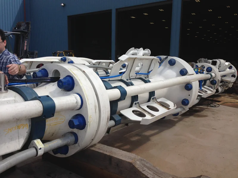
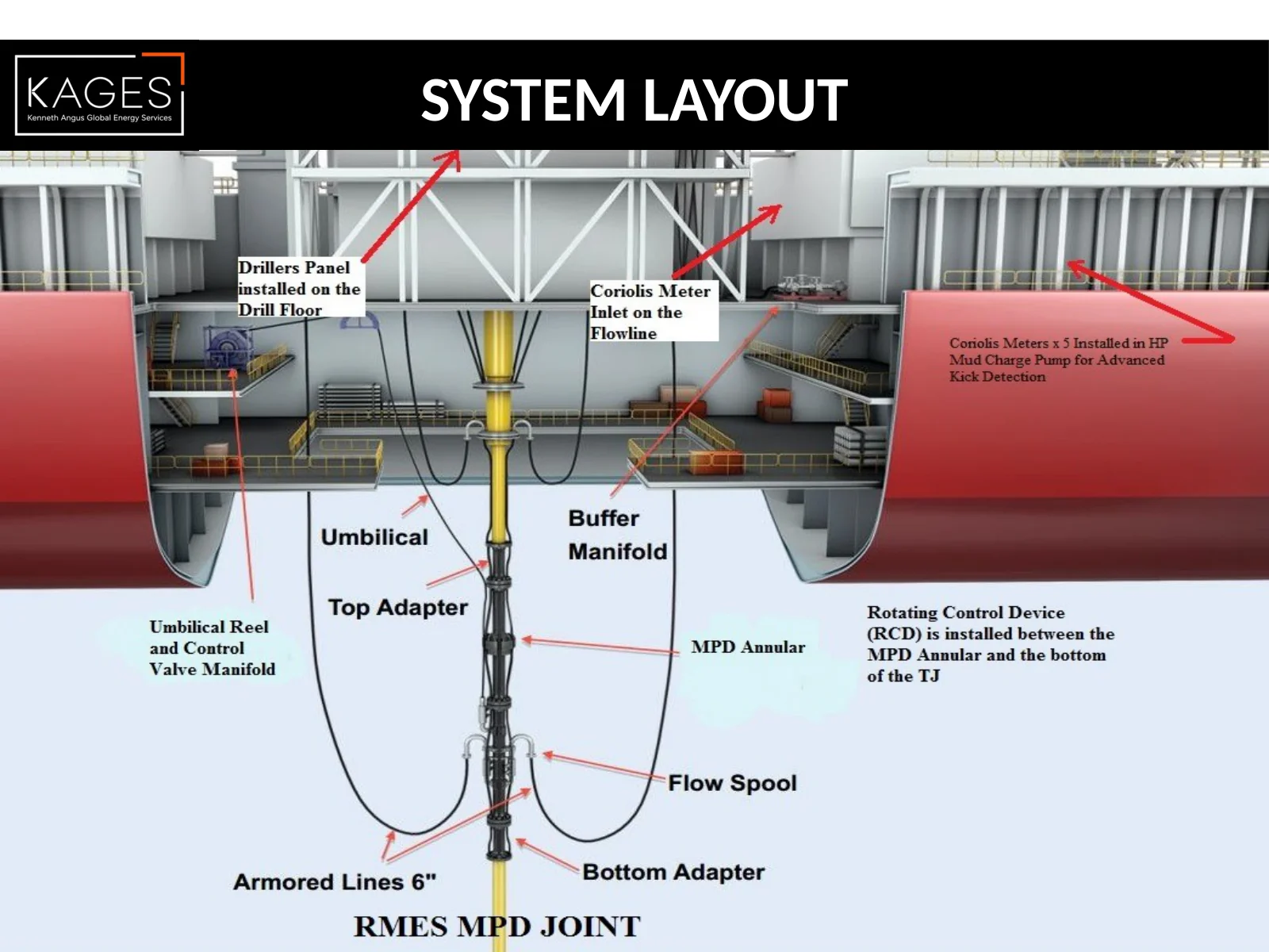
The system-layout diagram places the components in their vessel context. The equipment presentation covers the joint, rotating control device, annular, flow spool and manifold arrangements.
Configuration, vessel fit and operating limits are defined for the intended application. The MPD equipment is not intended for well-control operations.
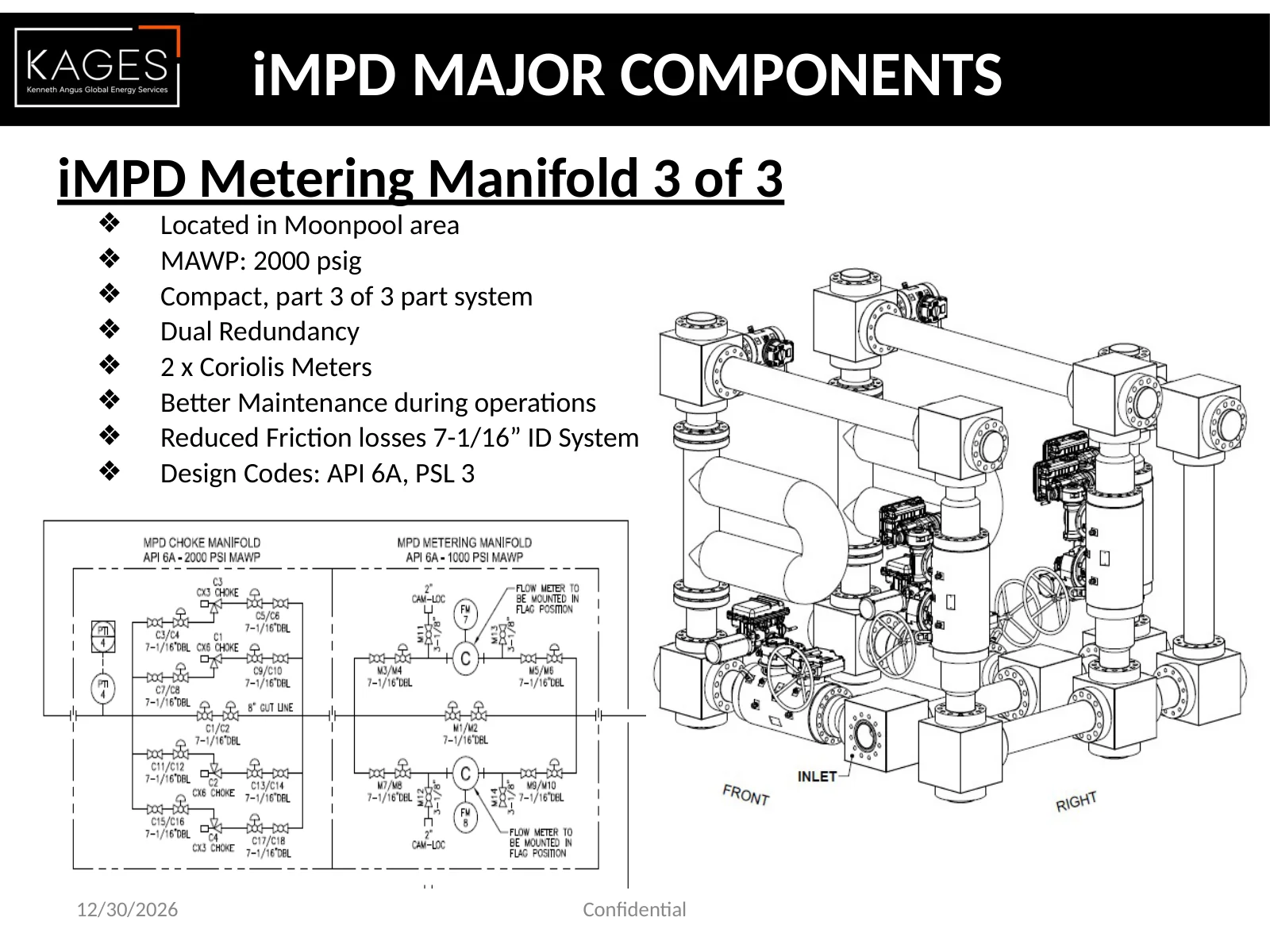
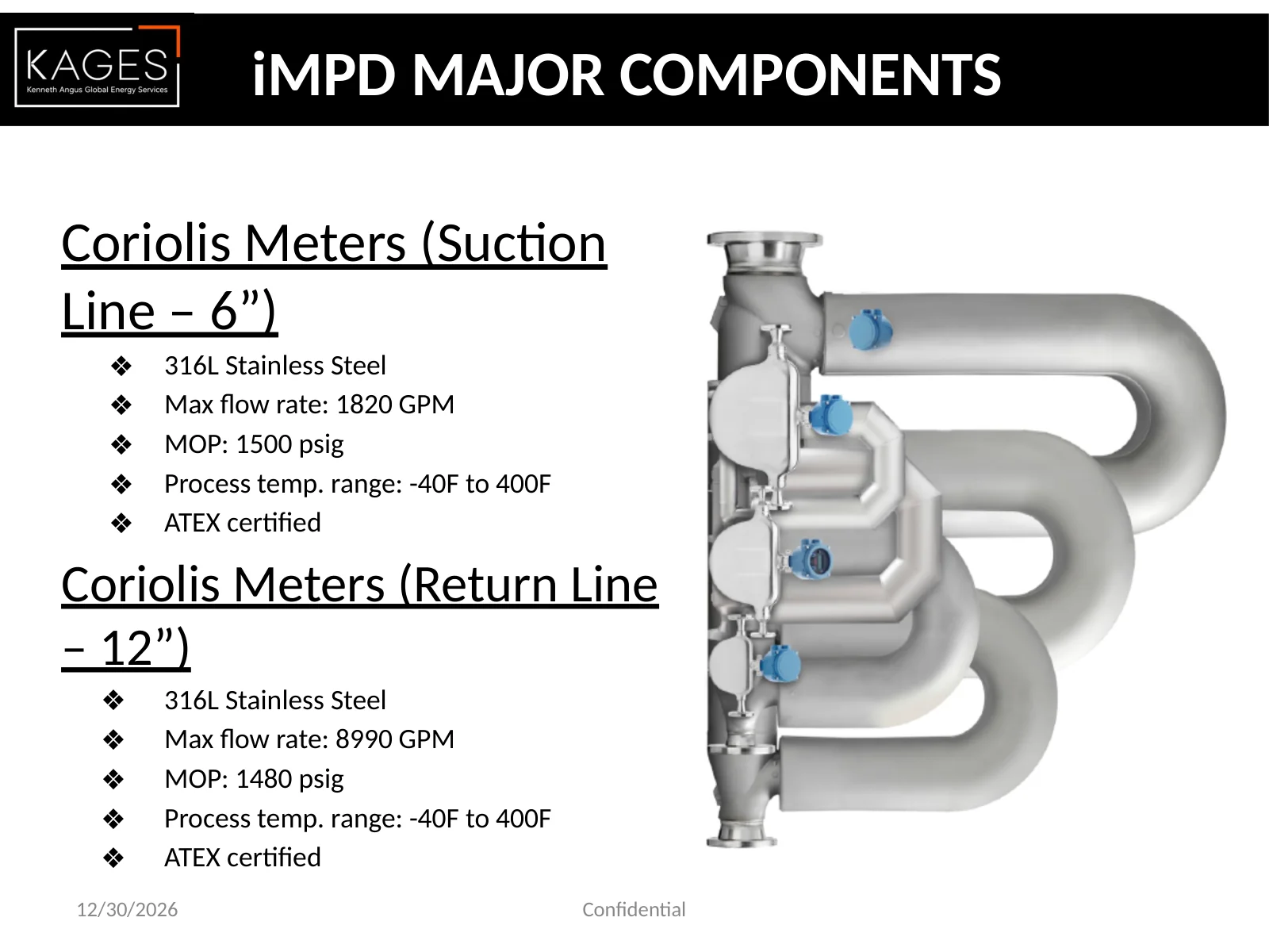
Metering and controls bring together flow, density, valve status, pressure and temperature information. The diagrams and equipment views show how these functions connect within the system arrangement.
KAGES’ MPD project training addresses concept, functional specifications, contracts, project execution, equipment requirements and shipyard installation. Read the dedicated Training section for the course scope.
Explore the Equipment and Implementation presentation, KAGES System Comparison and RCD Supplier and Product Assessment for equipment arrangements and comparative design considerations.
Discuss the vessel interfaces, equipment configuration and operating requirements with KAGES to define the engineering scope.
iMPD Equipment and Implementation
The system layout, equipment, monitoring and project implementation offer.
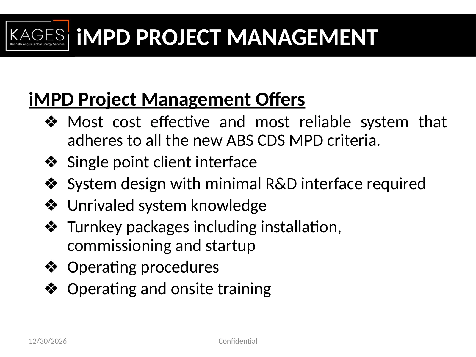
iMPD PROJECT MANAGEMENT iMPD Project Management Offers ❖Most cost effective and most reliable system that adheres to all the new ABS CDS MPD criteria. ❖Single point client interface ❖System design with minimal R&D interface required ❖Unrivaled system knowledge ❖Turnkey packages including installation, commissioning and startup ❖Operating procedures ❖Operating and onsite training 12/30/2026 Confidential
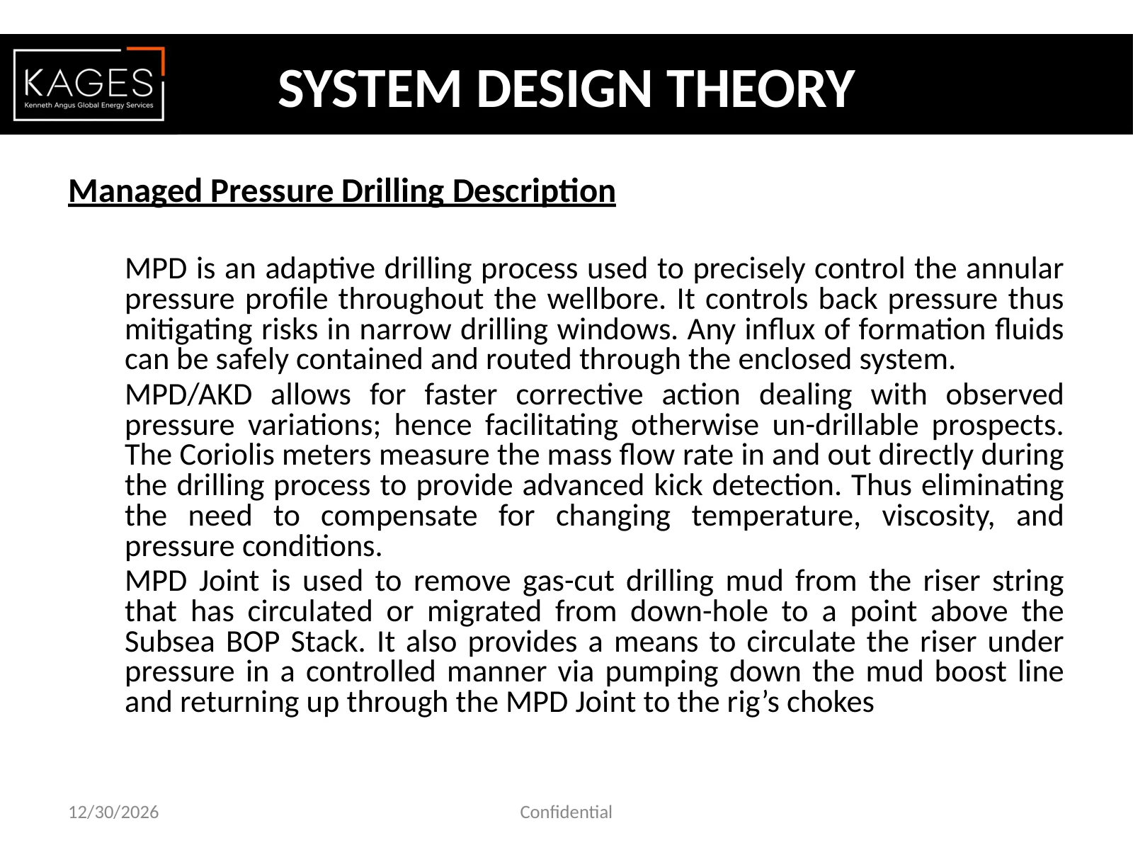
SYSTEM DESIGN THEORY Managed Pressure Drilling Description MPD is an adaptive drilling process used to precisely control the annular pressure profile throughout the wellbore. It controls back pressure thus mitigating risks in narrow drilling windows. Any influx of formation fluids can be safely contained and routed through the enclosed system. MPD/AKD allows for faster corrective action dealing with observed pressure variations; hence facilitating otherwise un-drillable prospects. The Coriolis meters measure the mass flow rate in and out directly during the drilling process to provide advanced kick detection. Thus eliminating the need to compensate for changing temperature, viscosity, and pressure conditions. MPD Joint is used to remove gas-cut drilling mud from the riser string that has circulated or migrated from down-hole to a point above the Subsea BOP Stack. It also provides a means to circulate the riser under pressure in a controlled manner via pumping down the mud boost line and returning up through the MPD Joint to the rig’s chokes 12/30/2026 Confidential
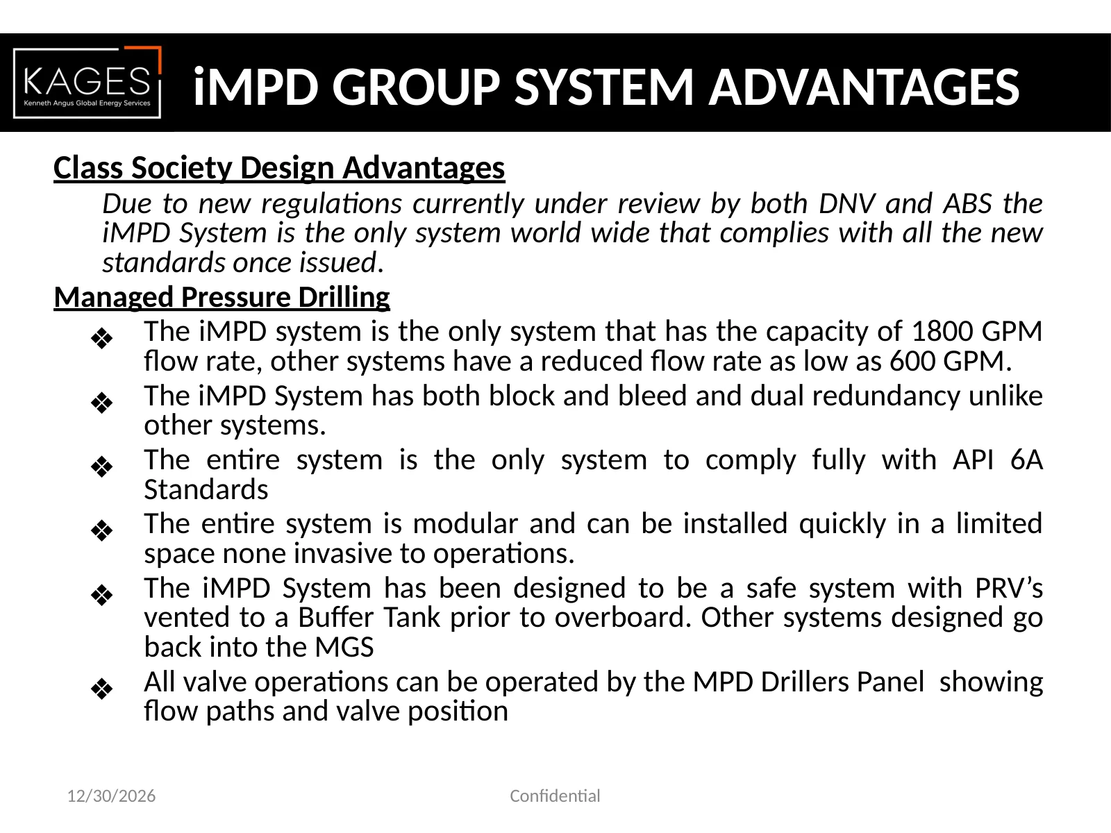
. iMPD GROUP SYSTEM ADVANTAGES Class Society Design Advantages Due to new regulations currently under review by both DNV and ABS the iMPD System is the only system world wide that complies with all the new standards once issued. Managed Pressure Drilling ❖ The iMPD system is the only system that has the capacity of 1800 GPM flow rate, other systems have a reduced flow rate as low as 600 GPM. ❖ The iMPD System has both block and bleed and dual redundancy unlike other systems. ❖ The entire system is the only system to comply fully with API 6A Standards ❖ The entire system is modular and can be installed quickly in a limited space none invasive to operations. ❖ The iMPD System has been designed to be a safe system with PRV’s vented to a Buffer Tank prior to overboard. Other systems designed go back into the MGS ❖ All valve operations can be operated by the MPD Drillers Panel showing flow paths and valve position 12/30/2026 Confidential
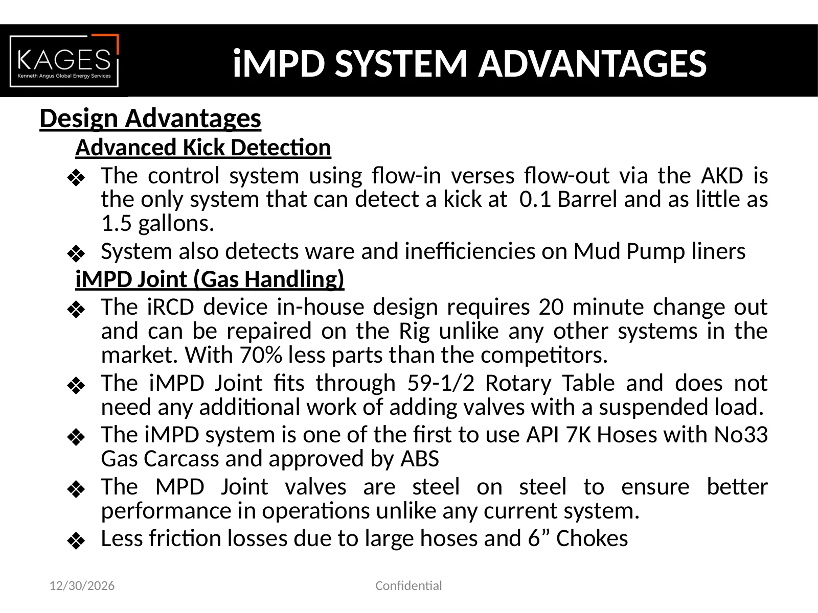
Design Advantages Advanced Kick Detection ❖The control system using flow-in verses flow-out via the AKD is the only system that can detect a kick at 0.1 Barrel and as little as 1.5 gallons. ❖System also detects ware and inefficiencies on Mud Pump liners iMPD Joint (Gas Handling) ❖The iRCD device in-house design requires 20 minute change out and can be repaired on the Rig unlike any other systems in the market. With 70% less parts than the competitors. ❖The iMPD Joint fits through 59-1/2 Rotary Table and does not need any additional work of adding valves with a suspended load. ❖The iMPD system is one of the first to use API 7K Hoses with No33 Gas Carcass and approved by ABS ❖The MPD Joint valves are steel on steel to ensure better performance in operations unlike any current system. ❖Less friction losses due to large hoses and 6” Chokes 12/30/2026 Confidential . iMPD SYSTEM ADVANTAGES
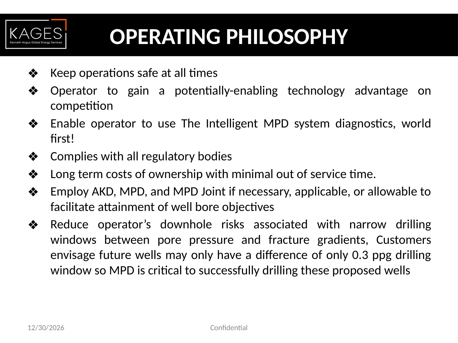
❖ Keep operations safe at all times ❖ Operator to gain a potentially-enabling technology advantage on competition ❖ Enable operator to use The Intelligent MPD system diagnostics, world first! ❖ Complies with all regulatory bodies ❖ Long term costs of ownership with minimal out of service time. ❖ Employ AKD, MPD, and MPD Joint if necessary, applicable, or allowable to facilitate attainment of well bore objectives ❖ Reduce operator’s downhole risks associated with narrow drilling windows between pore pressure and fracture gradients, Customers envisage future wells may only have a difference of only 0.3 ppg drilling window so MPD is critical to successfully drilling these proposed wells OPERATING PHILOSOPHY 12/30/2026 Confidential
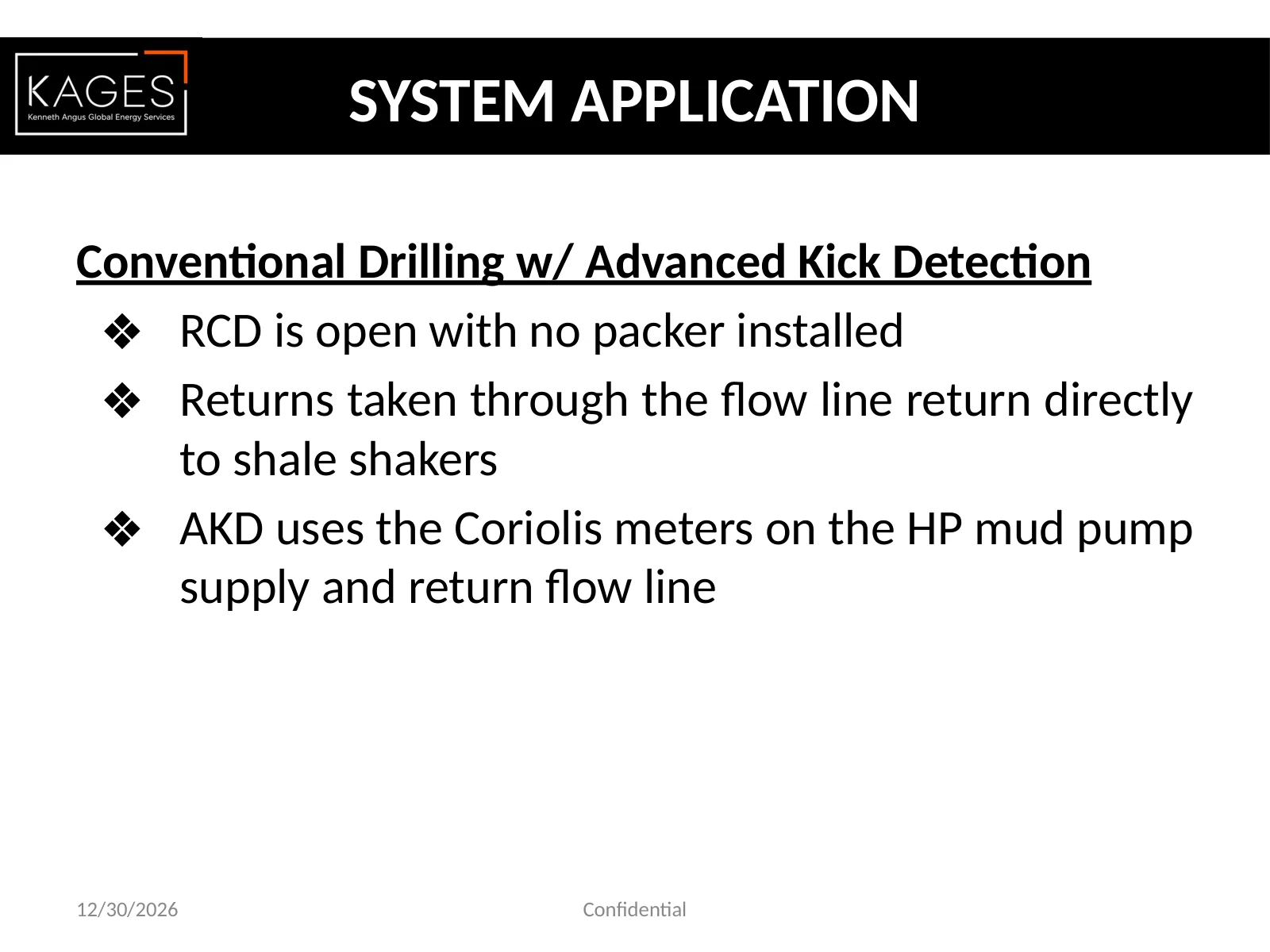
Conventional Drilling w/ Advanced Kick Detection ❖RCD is open with no packer installed ❖Returns taken through the flow line return directly to shale shakers ❖AKD uses the Coriolis meters on the HP mud pump supply and return flow line SYSTEM APPLICATION 12/30/2026 Confidential
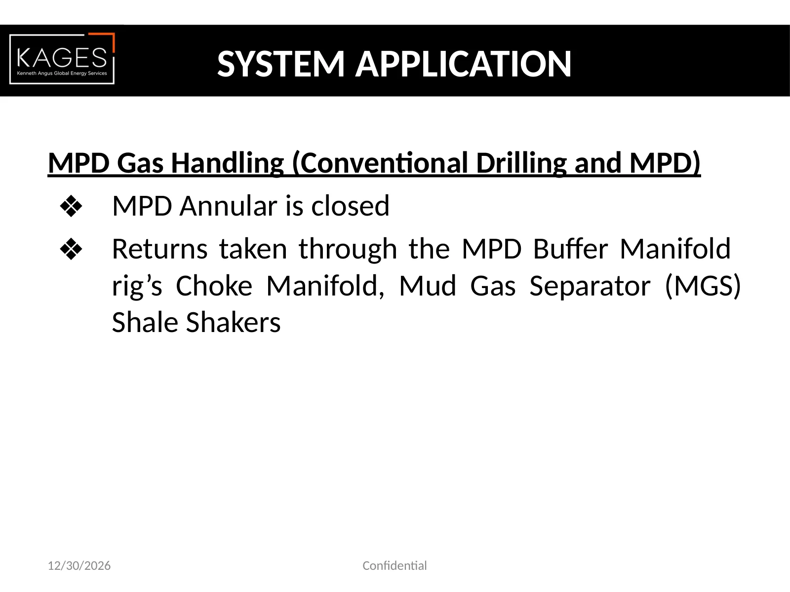
MPD Gas Handling (Conventional Drilling and MPD) ❖ MPD Annular is closed ❖ Returns taken through the MPD Buffer Manifold rig’s Choke Manifold, Mud Gas Separator (MGS) Shale Shakers 12/30/2026 Confidential SYSTEM APPLICATION
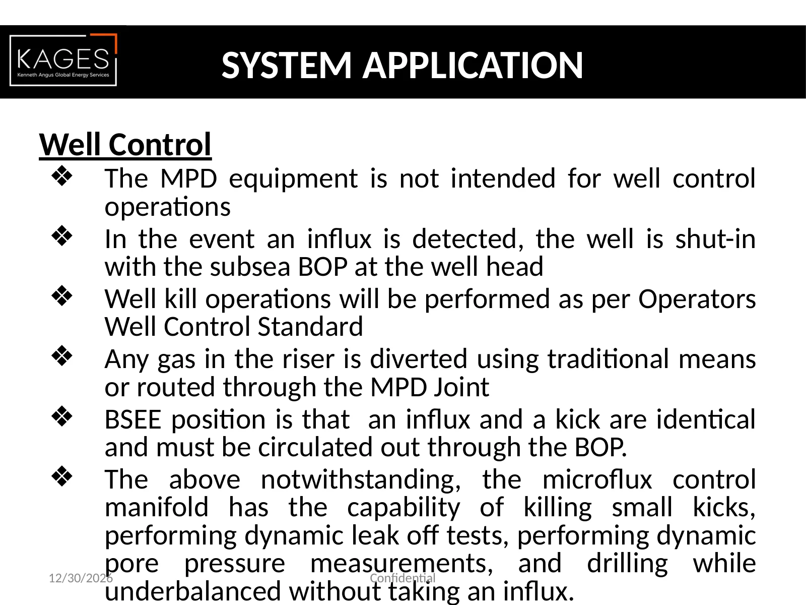
Well Control ❖ The MPD equipment is not intended for well control operations ❖ In the event an influx is detected, the well is shut-in with the subsea BOP at the well head ❖ Well kill operations will be performed as per Operators Well Control Standard ❖ Any gas in the riser is diverted using traditional means or routed through the MPD Joint ❖ BSEE position is that an influx and a kick are identical and must be circulated out through the BOP. ❖ The above notwithstanding, the microflux control manifold has the capability of killing small kicks, performing dynamic leak off tests, performing dynamic pore pressure measurements, and drilling while underbalanced without taking an influx. 12/30/2026 Confidential SYSTEM APPLICATION
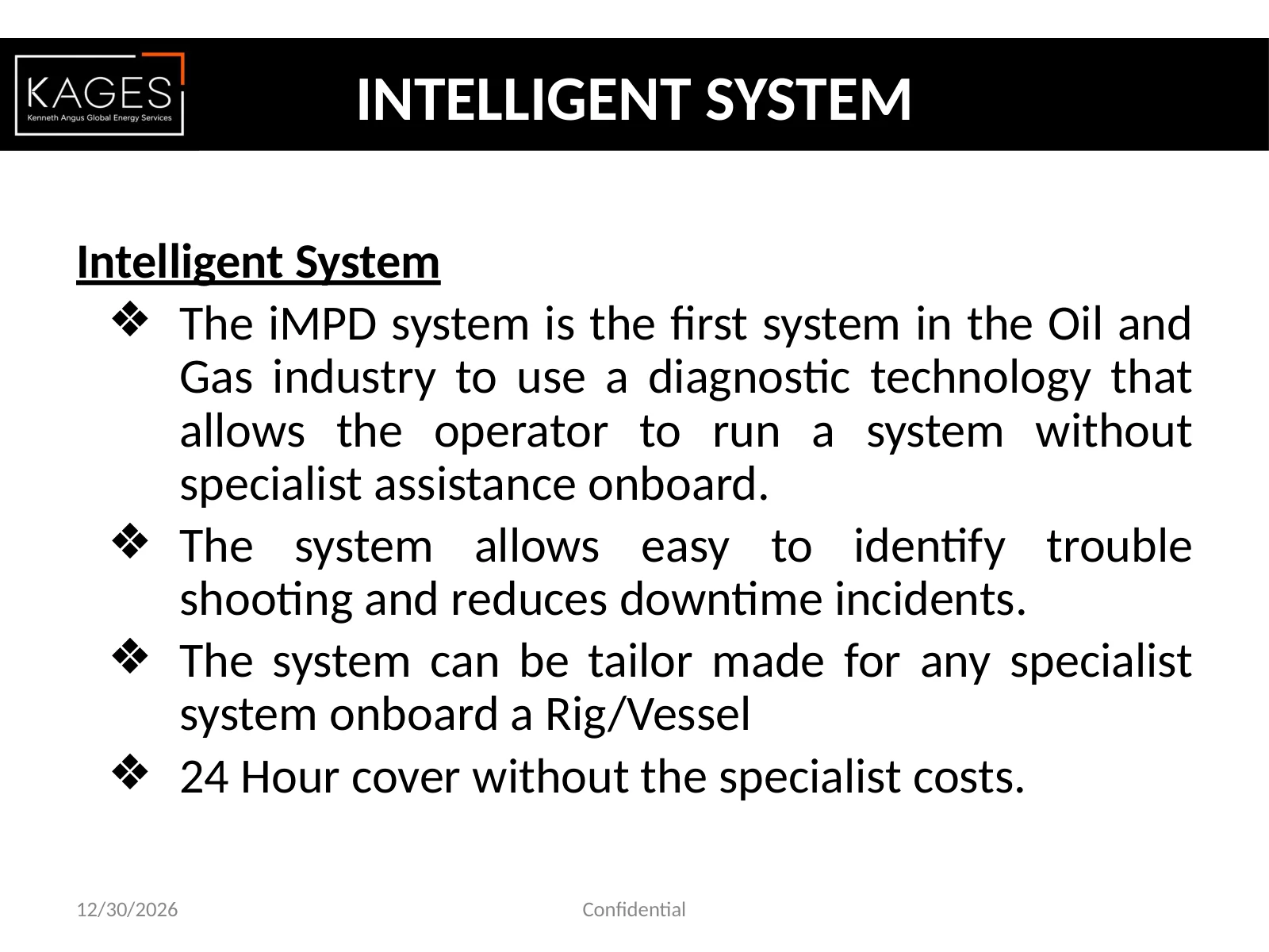
INTELLIGENT SYSTEM Intelligent System ❖The iMPD system is the first system in the Oil and Gas industry to use a diagnostic technology that allows the operator to run a system without specialist assistance onboard. ❖The system allows easy to identify trouble shooting and reduces downtime incidents. ❖The system can be tailor made for any specialist system onboard a Rig/Vessel ❖24 Hour cover without the specialist costs. 12/30/2026 Confidential
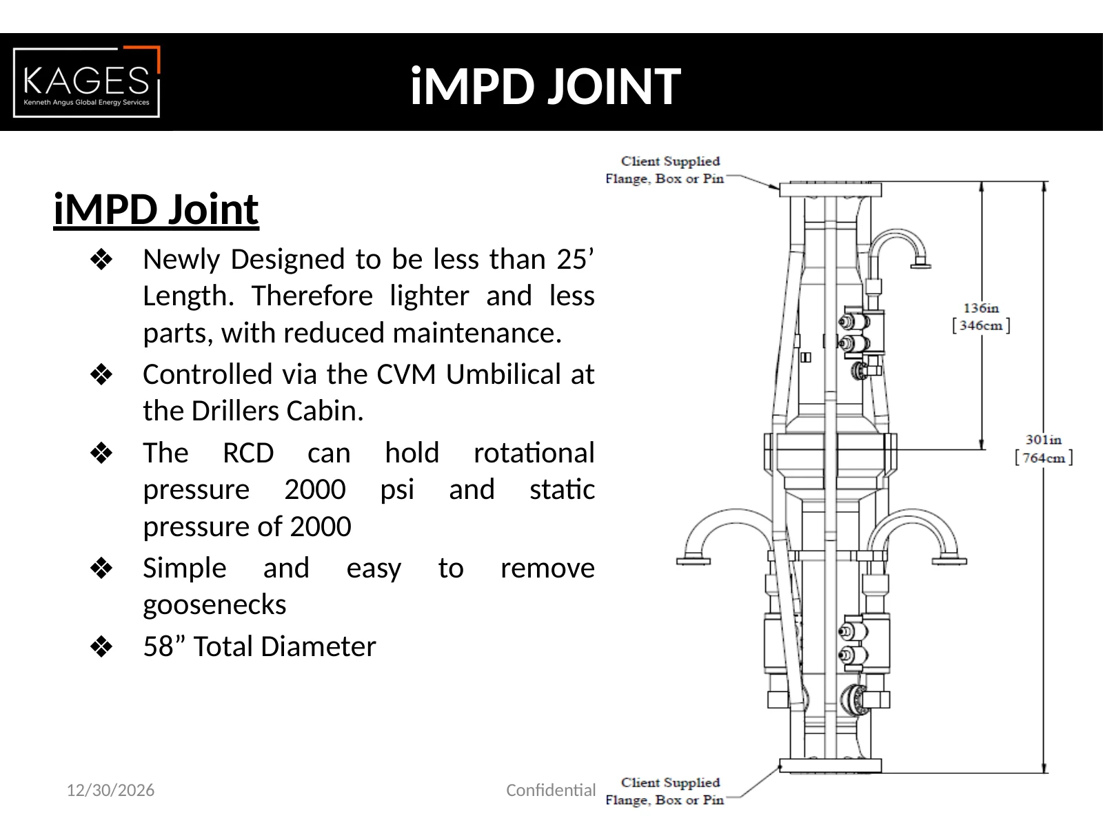
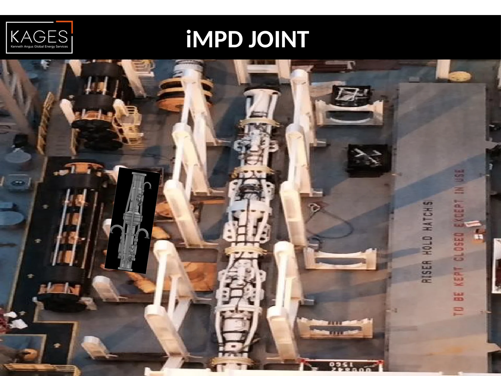
iMPD JOINT iMPD Joint ❖ Newly Designed to be less than 25’ Length. Therefore lighter and less parts, with reduced maintenance. ❖ Controlled via the CVM Umbilical at the Drillers Cabin. ❖ The RCD can hold rotational pressure 2000 psi and static pressure of 2000 ❖ Simple and easy to remove goosenecks ❖ 58” Total Diameter 12/30/2026 Confidential
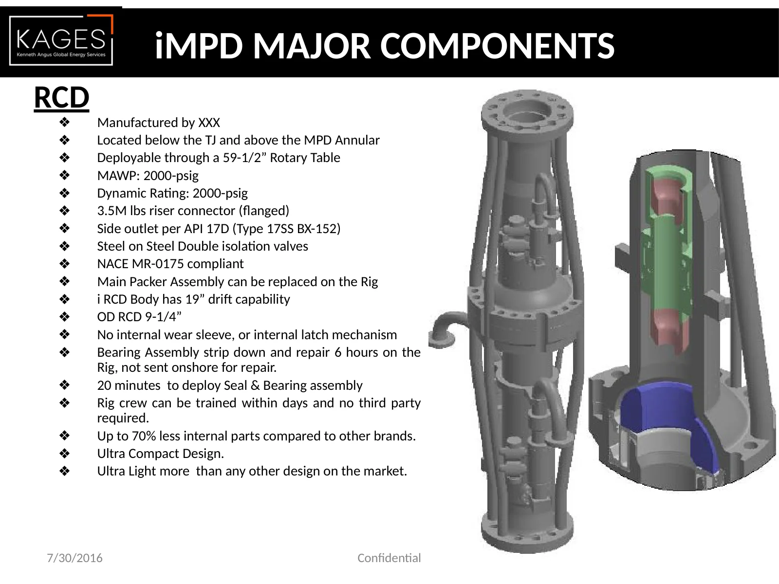
RCD ❖ Manufactured by XXX ❖ Located below the TJ and above the MPD Annular ❖ Deployable through a 59-1/2” Rotary Table ❖ MAWP: 2000-psig ❖ Dynamic Rating: 2000-psig ❖ 3.5M lbs riser connector (flanged) ❖ Side outlet per API 17D (Type 17SS BX-152) ❖ Steel on Steel Double isolation valves ❖ NACE MR-0175 compliant ❖ Main Packer Assembly can be replaced on the Rig ❖ i RCD Body has 19” drift capability ❖ OD RCD 9-1/4” ❖ No internal wear sleeve, or internal latch mechanism ❖ Bearing Assembly strip down and repair 6 hours on the Rig, not sent onshore for repair. ❖ 20 minutes to deploy Seal & Bearing assembly ❖ Rig crew can be trained within days and no third party required. ❖ Up to 70% less internal parts compared to other brands. ❖ Ultra Compact Design. ❖ Ultra Light more than any other design on the market. Major Components 7/30/2016 Confidential iMPD MAJOR COMPONENTS
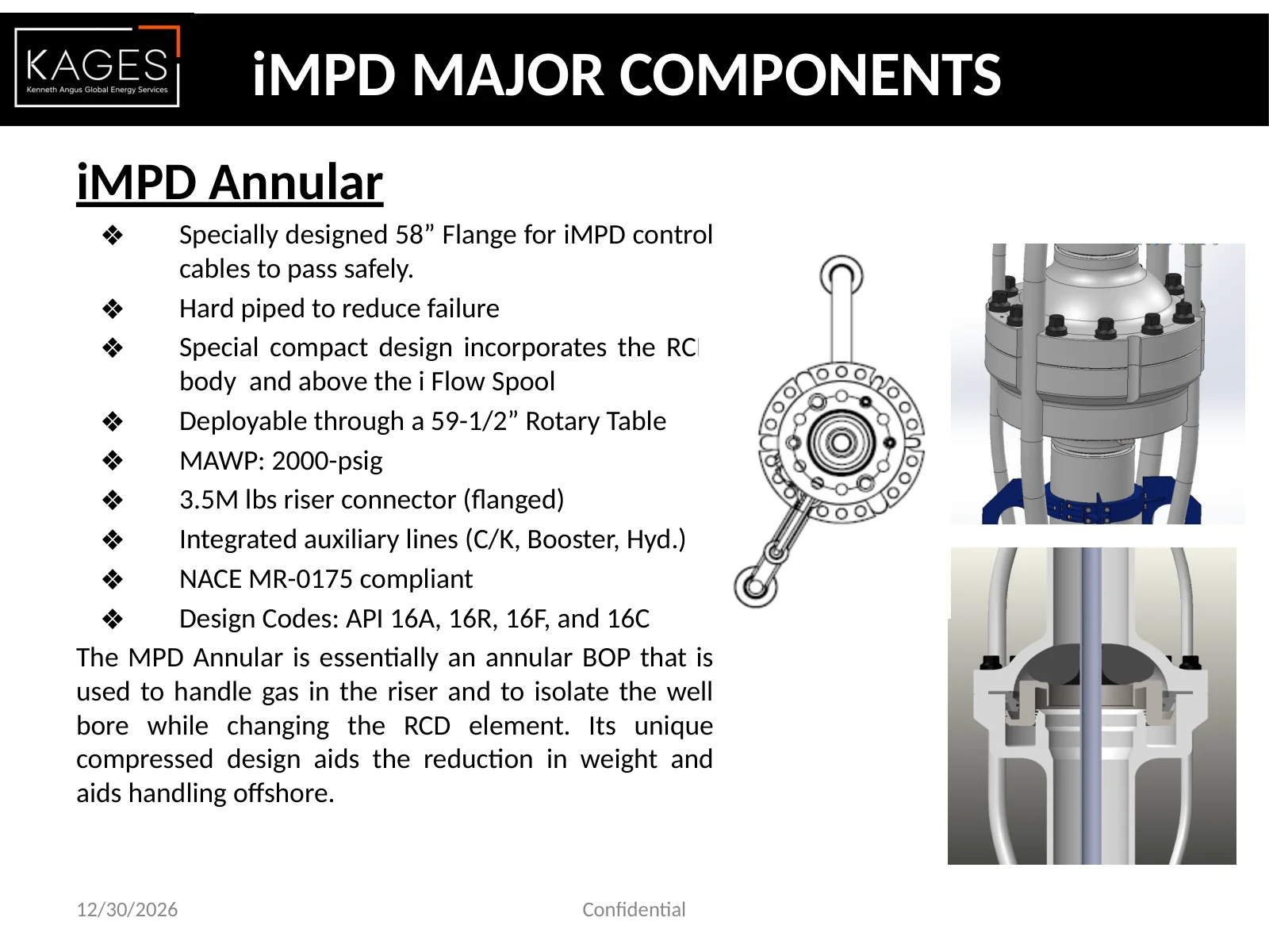
iMPD Annular ❖ Specially designed 58” Flange for iMPD control cables to pass safely. ❖ Hard piped to reduce failure ❖ Special compact design incorporates the RCD body and above the i Flow Spool ❖ Deployable through a 59-1/2” Rotary Table ❖ MAWP: 2000-psig ❖ 3.5M lbs riser connector (flanged) ❖ Integrated auxiliary lines (C/K, Booster, Hyd.) ❖ NACE MR-0175 compliant ❖ Design Codes: API 16A, 16R, 16F, and 16C The MPD Annular is essentially an annular BOP that is used to handle gas in the riser and to isolate the well bore while changing the RCD element. Its unique compressed design aids the reduction in weight and aids handling offshore. Major Components 12/30/2026 Confidential iMPD MAJOR COMPONENTS
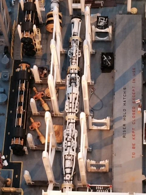
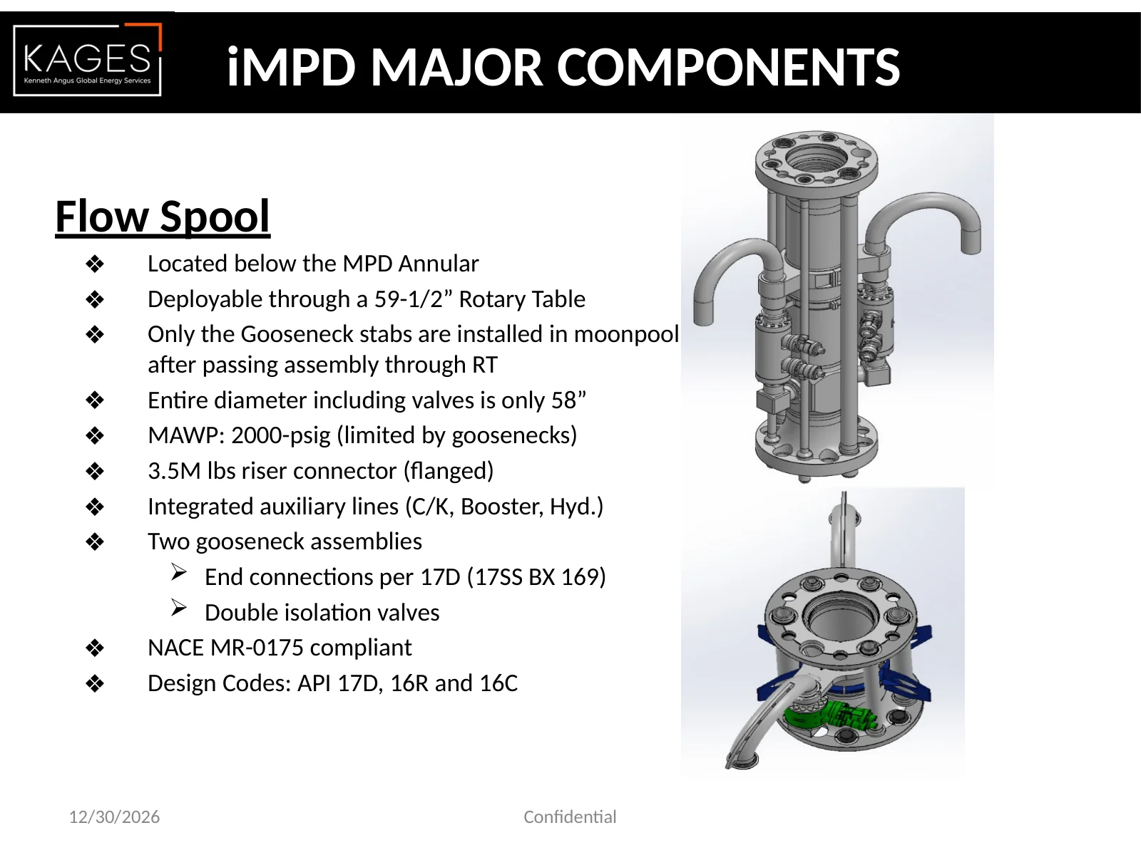
Flow Spool ❖ Located below the MPD Annular ❖ Deployable through a 59-1/2” Rotary Table ❖ Only the Gooseneck stabs are installed in moonpool after passing assembly through RT ❖ Entire diameter including valves is only 58” ❖ MAWP: 2000-psig (limited by goosenecks) ❖ 3.5M lbs riser connector (flanged) ❖ Integrated auxiliary lines (C/K, Booster, Hyd.) ❖ Two gooseneck assemblies End connections per 17D (17SS BX 169) Double isolation valves ❖ NACE MR-0175 compliant ❖ Design Codes: API 17D, 16R and 16C 12/30/2026 Confidential iMPD MAJOR COMPONENTS
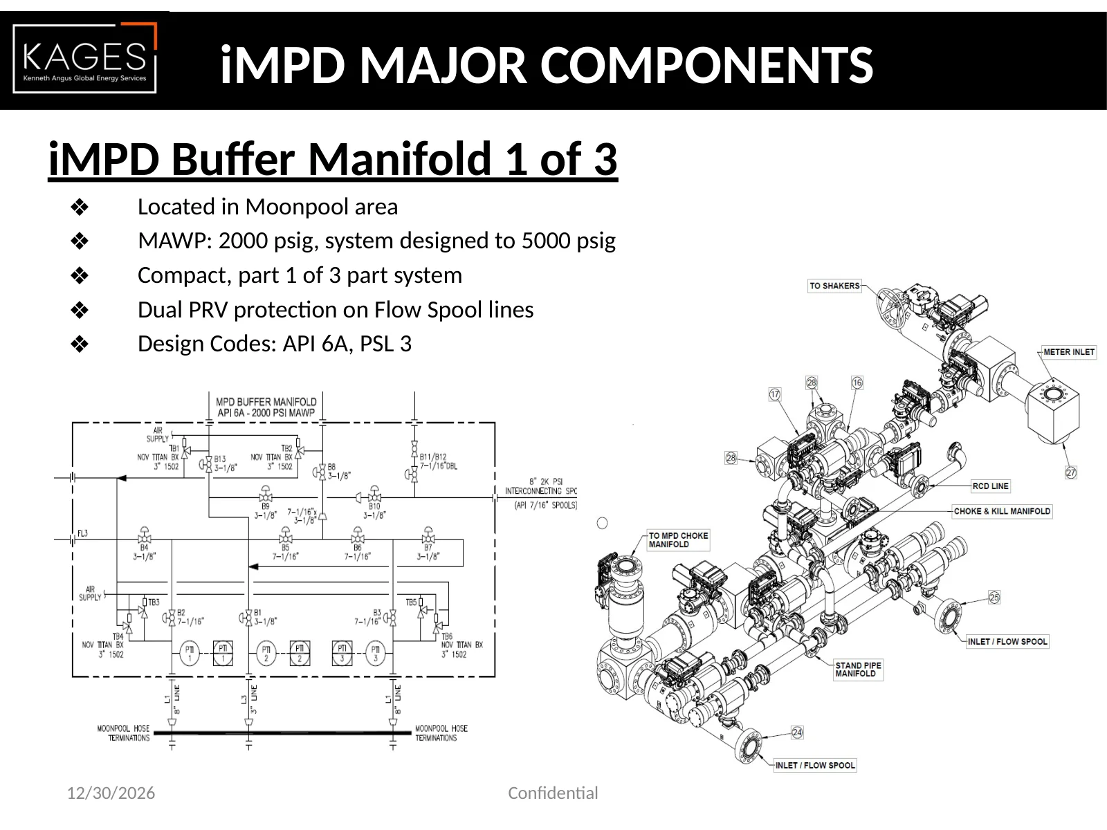
iMPD Buffer Manifold 1 of 3 ❖ Located in Moonpool area ❖ MAWP: 2000 psig, system designed to 5000 psig ❖ Compact, part 1 of 3 part system ❖ Dual PRV protection on Flow Spool lines ❖ Design Codes: API 6A, PSL 3 12/30/2026 Confidential iMPD MAJOR COMPONENTS
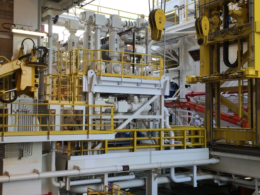
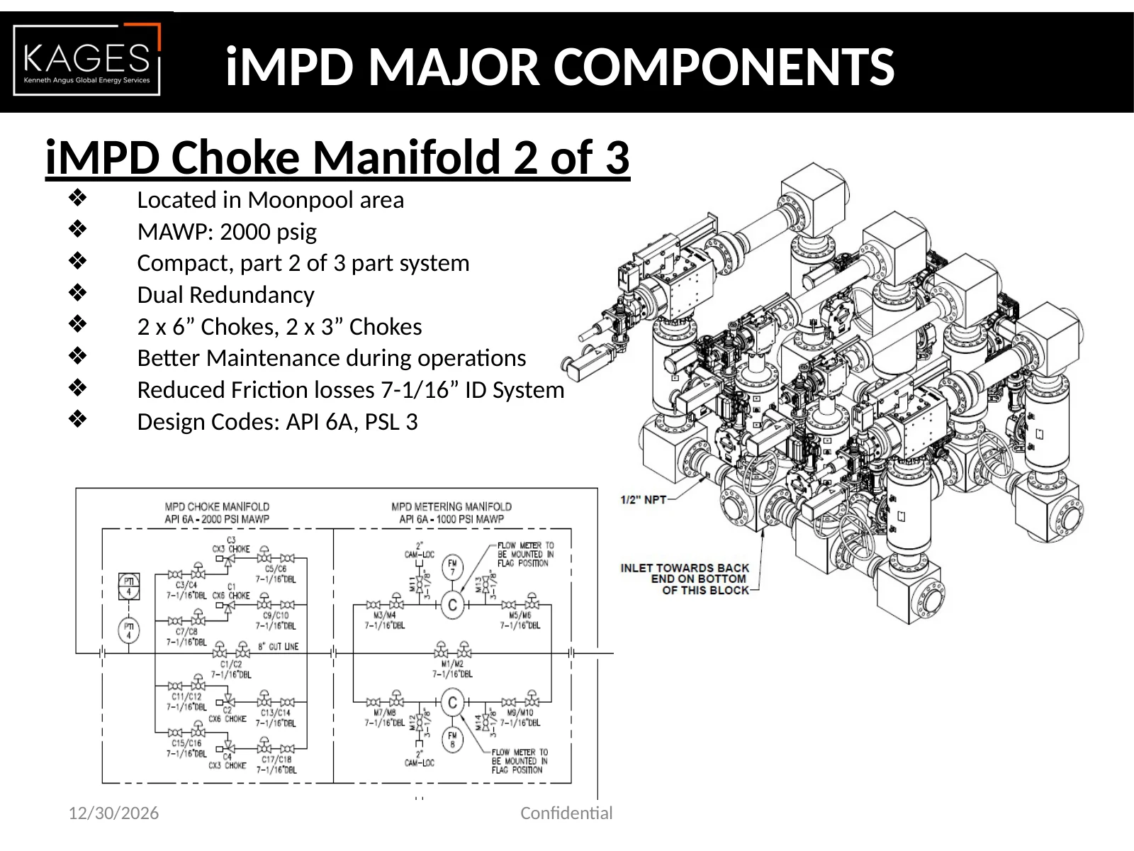
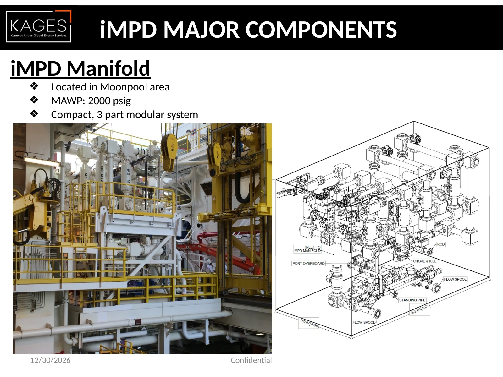
12/30/2026 Confidential iMPD MAJOR COMPONENTS iMPD Choke Manifold 2 of 3 ❖ Located in Moonpool area ❖ MAWP: 2000 psig ❖ Compact, part 2 of 3 part system ❖ Dual Redundancy ❖ 2 x 6” Chokes, 2 x 3” Chokes ❖ Better Maintenance during operations ❖ Reduced Friction losses 7-1/16” ID System ❖ Design Codes: API 6A, PSL 3
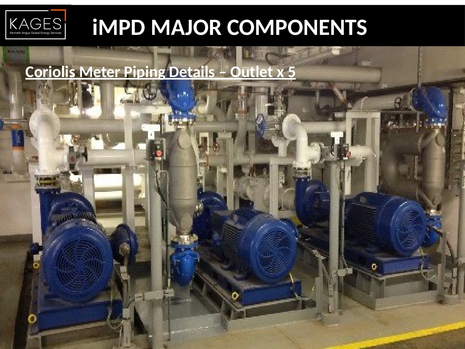
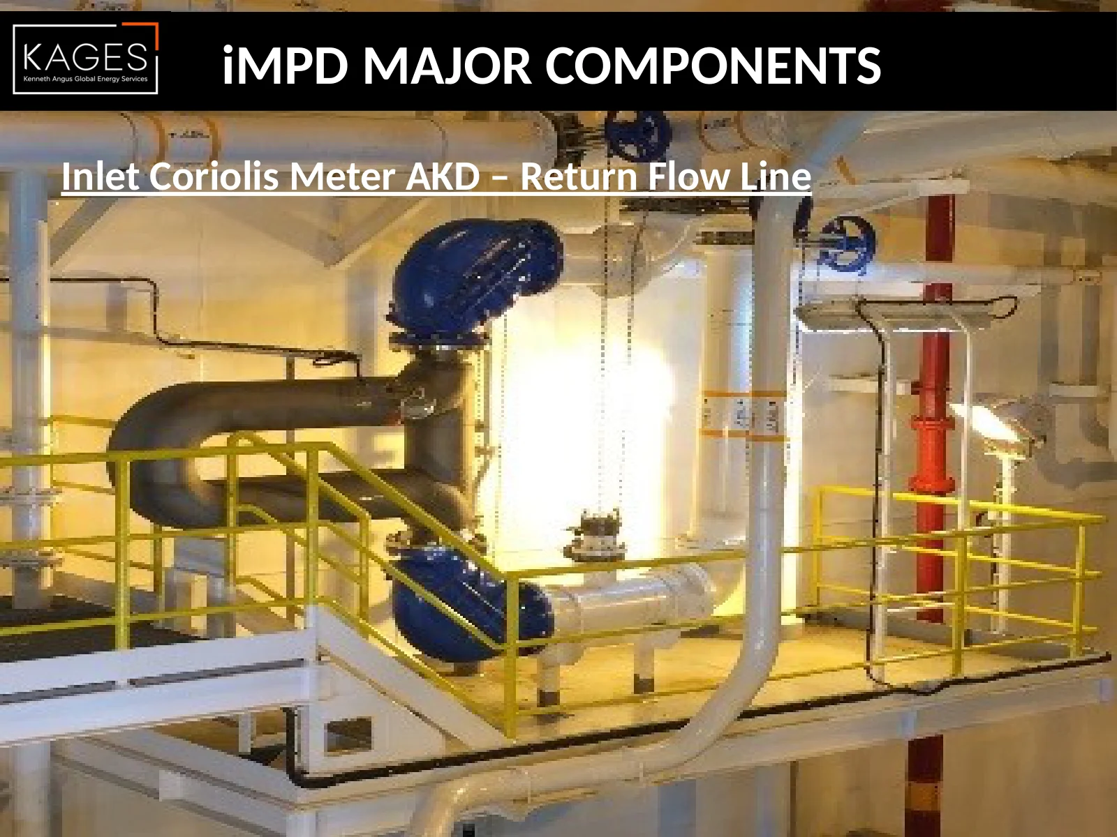
12/30/2026 Confidential iMPD MAJOR COMPONENTS iMPD Metering Manifold 3 of 3 ❖ Located in Moonpool area ❖ MAWP: 2000 psig ❖ Compact, part 3 of 3 part system ❖ Dual Redundancy ❖ 2 x Coriolis Meters ❖ Better Maintenance during operations ❖ Reduced Friction losses 7-1/16” ID System ❖ Design Codes: API 6A, PSL 3
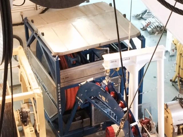
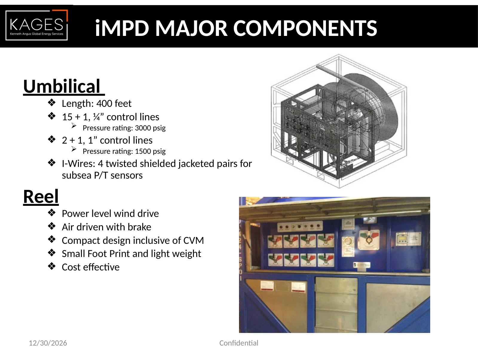
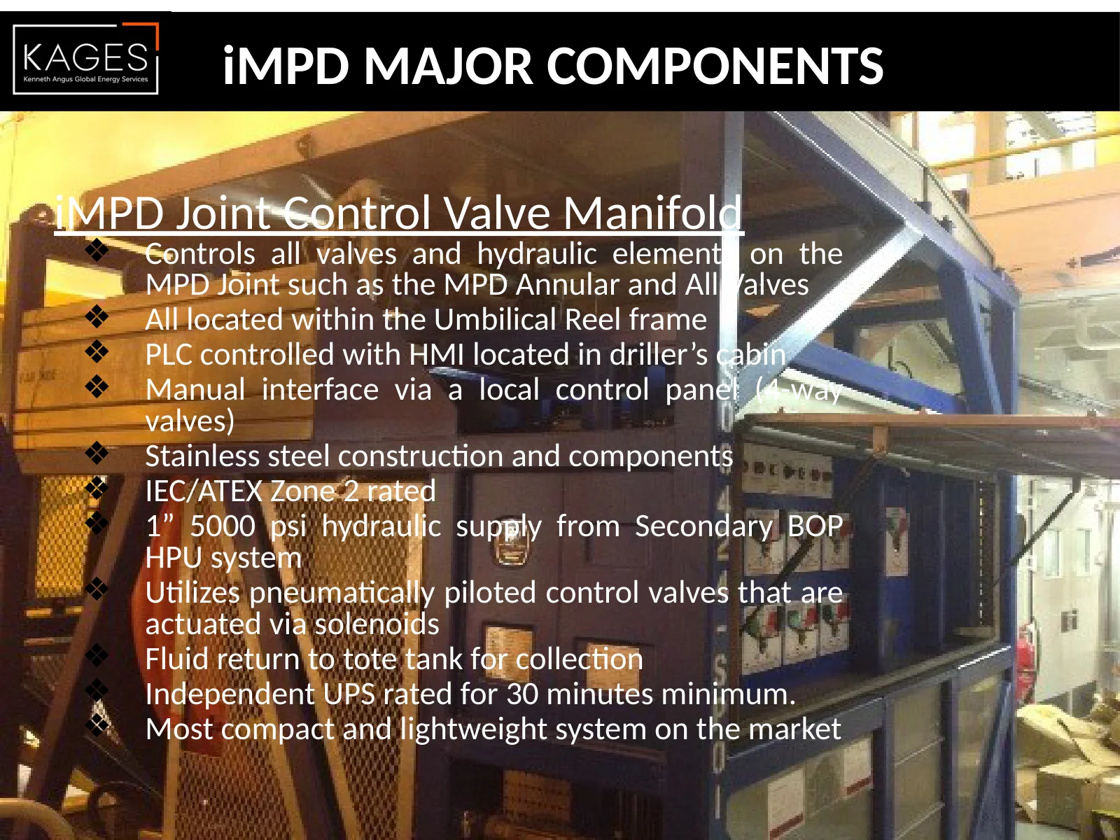
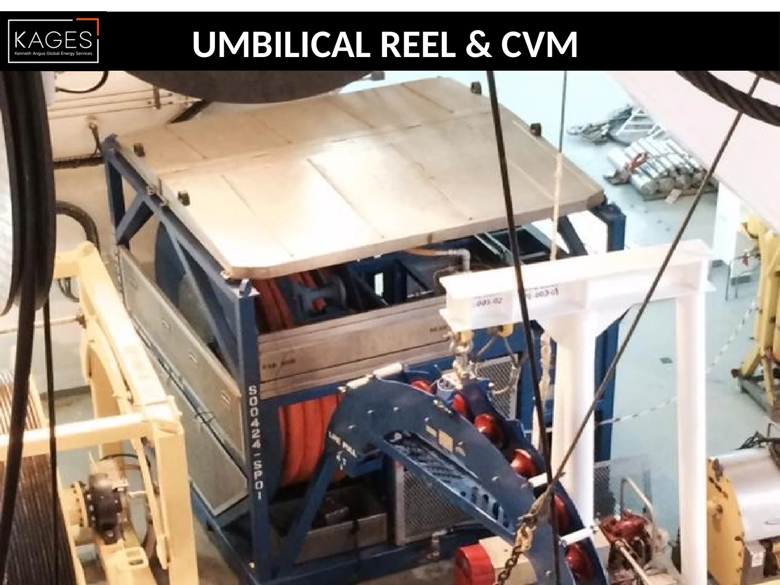
12/30/2026 Confidential iMPD MAJOR COMPONENTS iMPD Joint Control Valve Manifold ❖ Controls all valves and hydraulic elements on the MPD Joint such as the MPD Annular and All Valves ❖ All located within the Umbilical Reel frame ❖ PLC controlled with HMI located in driller’s cabin ❖ Manual interface via a local control panel (4-way valves) ❖ Stainless steel construction and components ❖ IEC/ATEX Zone 2 rated ❖ 1” 5000 psi hydraulic supply from Secondary BOP HPU system ❖ Utilizes pneumatically piloted control valves that are actuated via solenoids ❖ Fluid return to tote tank for collection ❖ Independent UPS rated for 30 minutes minimum. ❖ Most compact and lightweight system on the market
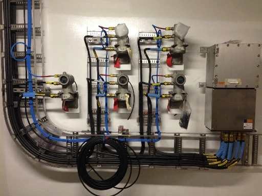
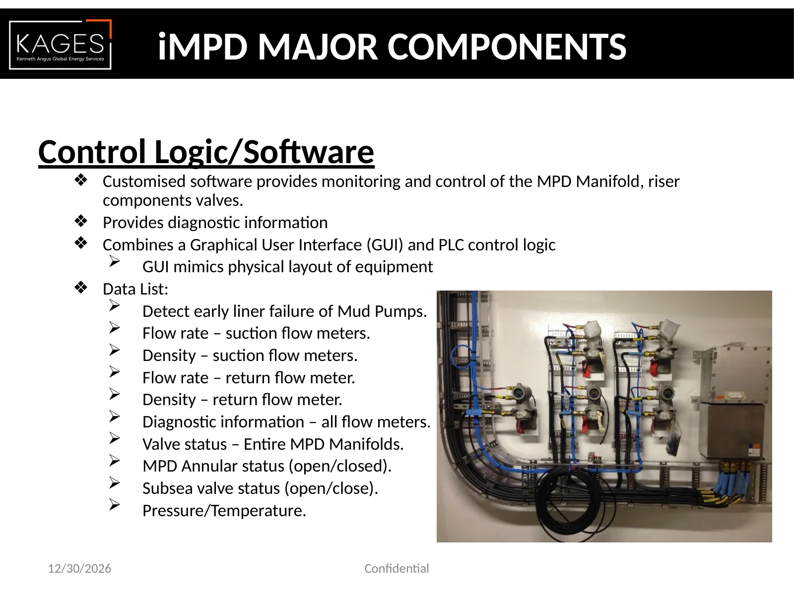
Control Logic/Software ❖Customised software provides monitoring and control of the MPD Manifold, riser components valves. ❖Provides diagnostic information ❖Combines a Graphical User Interface (GUI) and PLC control logic GUI mimics physical layout of equipment ❖Data List: Detect early liner failure of Mud Pumps. Flow rate – suction flow meters. Density – suction flow meters. Flow rate – return flow meter. Density – return flow meter. Diagnostic information – all flow meters. Valve status – Entire MPD Manifolds. MPD Annular status (open/closed). Subsea valve status (open/close). Pressure/Temperature. 12/30/2026 Confidential iMPD MAJOR COMPONENTS
SYSTEM DESIGN – ADDITIONAL COMPONENTS ❖Pressurised Junk Catcher system, returns from the well, pass through strainers prior to entering in MPD Manifold ❖Retro fitted sensors to existing Rig Choke Manifold to enable the driller determine exact flow path. ❖Well Magnets to aid Drill Crew to aid understanding well data received. 12/30/2026 Confidential
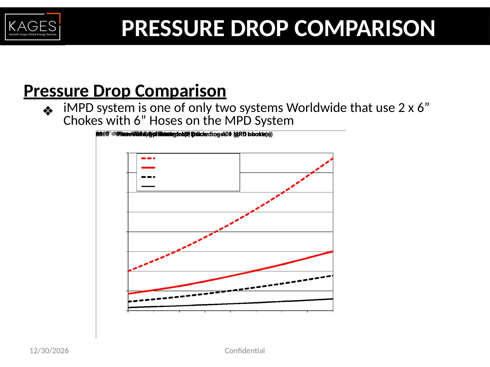
Pressure Drop Comparison ❖iMPD system is one of only two systems Worldwide that use 2 x 6” Chokes with 6” Hoses on the MPD System . PRESSURE DROP COMPARISON 12/30/2026 Confidential
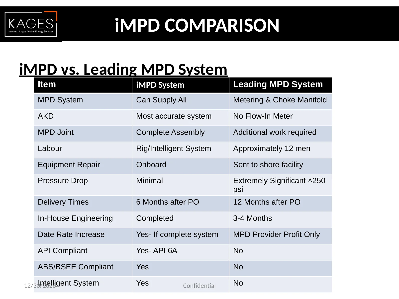
iMPD vs. Leading MPD System iMPD COMPARISON Item iMPD System Leading MPD System MPD System Can Supply All Metering & Choke Manifold AKD Most accurate system No Flow-In Meter MPD Joint Complete Assembly Additional work required Labour Rig/Intelligent System Approximately 12 men Equipment Repair Onboard Sent to shore facility Pressure Drop Minimal Extremely Significant ˄250 psi Delivery Times 6 Months after PO 12 Months after PO In-House Engineering Completed 3-4 Months Date Rate Increase Yes- If complete system MPD Provider Profit Only API Compliant Yes- API 6A No ABS/BSEE Compliant Yes No Intelligent System Yes No 12/30/2026 Confidential
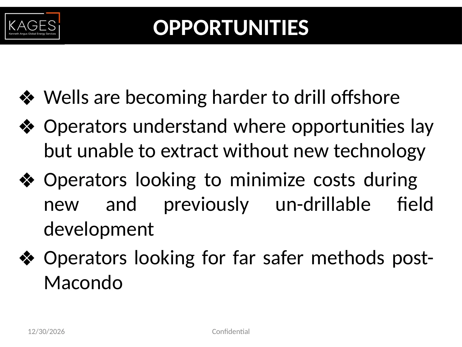
OPPORTUNITIES ❖Wells are becoming harder to drill offshore ❖Operators understand where opportunities lay but unable to extract without new technology ❖Operators looking to minimize costs during new and previously un-drillable field development ❖Operators looking for far safer methods post- Macondo 12/30/2026 Confidential
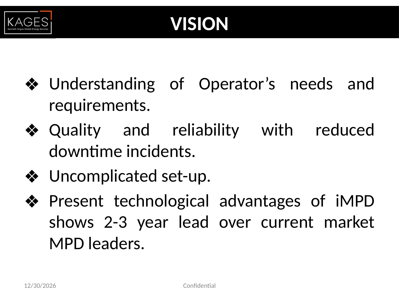
VISION ❖Understanding of Operator’s needs and requirements. ❖Quality and reliability with reduced downtime incidents. ❖Uncomplicated set-up. ❖Present technological advantages of iMPD shows 2-3 year lead over current market MPD leaders. 12/30/2026 Confidential
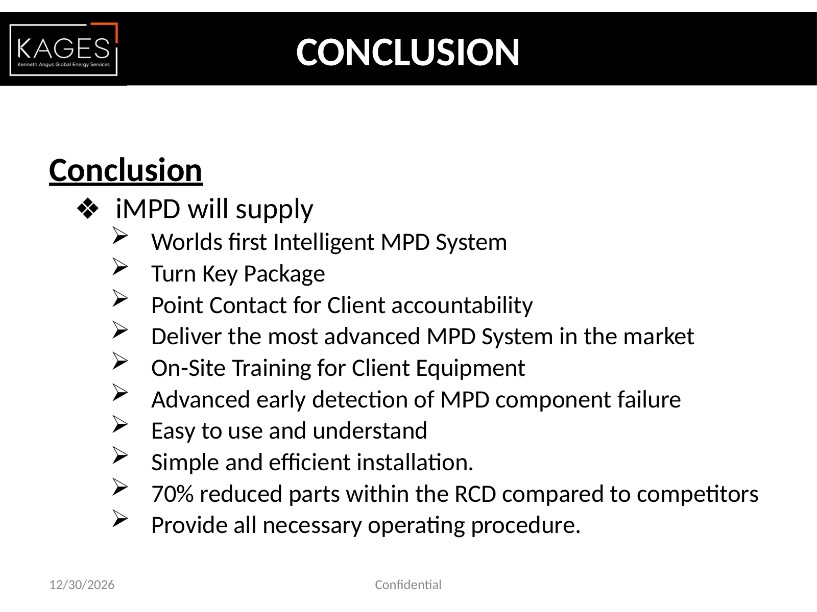
Conclusion ❖iMPD will supply Worlds first Intelligent MPD System Turn Key Package Point Contact for Client accountability Deliver the most advanced MPD System in the market On-Site Training for Client Equipment Advanced early detection of MPD component failure Easy to use and understand Simple and efficient installation. 70% reduced parts within the RCD compared to competitors Provide all necessary operating procedure. CONCLUSION 12/30/2026 Confidential
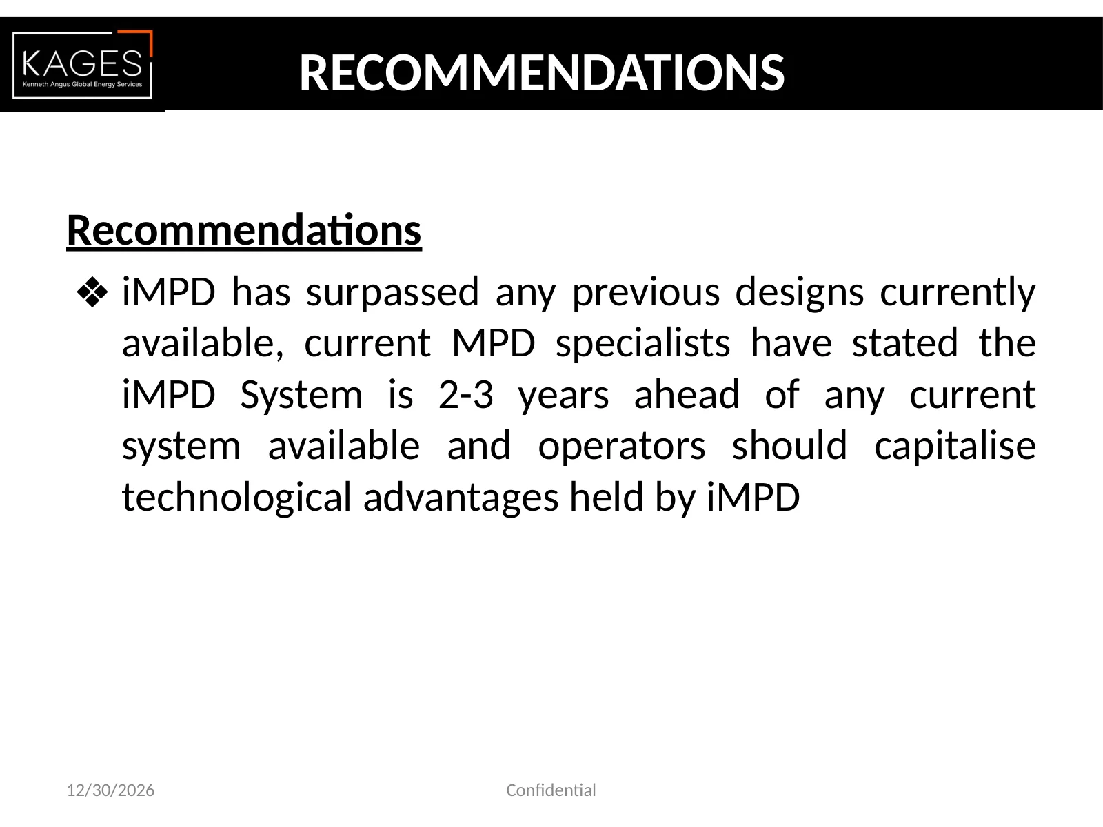
Recommendations ❖iMPD has surpassed any previous designs currently available, current MPD specialists have stated the iMPD System is 2-3 years ahead of any current system available and operators should capitalise technological advantages held by iMPD RECOMMENDATIONS 12/30/2026 Confidential
Relevant Expertise and Project Support
Let’s talk
Discuss an MPD Project
Share the intended application and the questions that need establishing.

 Enlarge page 6
 Enlarge page 15
 Enlarge page 22
 Enlarge page 24
 Enlarge Source equipment visual in the iMPD Equipment presentation, slide 16
 Enlarge Source equipment visual in the iMPD Equipment presentation, slide 23
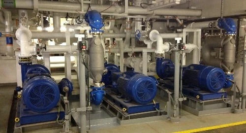 Enlarge Source equipment visual in the iMPD Equipment presentation, slide 25
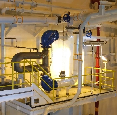 Enlarge Source equipment visual in the iMPD Equipment presentation, slide 26
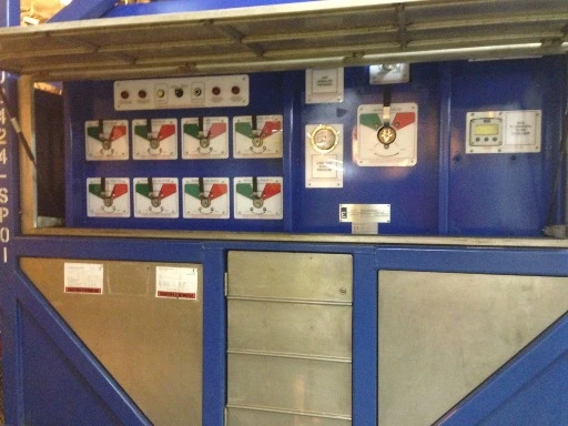 Enlarge Source equipment visual in the iMPD Equipment presentation, slide 27
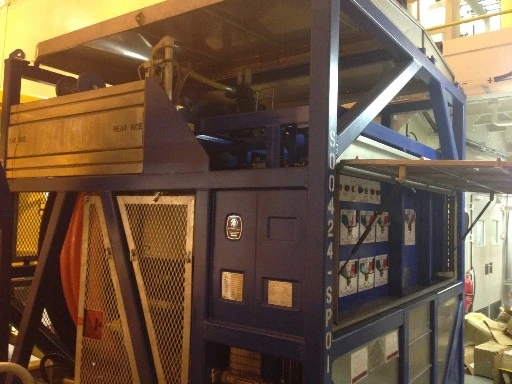 Enlarge Source equipment visual in the iMPD Equipment presentation, slide 28
 Enlarge Source equipment visual in the iMPD Equipment presentation, slide 29
 Enlarge Source equipment visual in the iMPD Equipment presentation, slide 30
 Enlarge page 1
 Enlarge page 2
 Enlarge page 3
 Enlarge page 4
 Enlarge page 5
 Enlarge page 7
 Enlarge page 8
 Enlarge page 9
 Enlarge page 10
 Enlarge page 11
 Enlarge page 12
 Enlarge page 13
 Enlarge page 14
 Enlarge page 16
 Enlarge page 17
 Enlarge page 18
 Enlarge page 19
 Enlarge page 20
 Enlarge page 21
 Enlarge page 23
 Enlarge page 25
 Enlarge page 26
 Enlarge page 27
 Enlarge page 28
 Enlarge page 29
 Enlarge page 30
 Enlarge page 31
 Enlarge page 32
 Enlarge page 33
 Enlarge page 34
 Enlarge page 35
 Enlarge page 36
 Enlarge page 37